Functional principle of a directional coupler
In a simplified model we will describe the fundamentals of coaxial directional couplers with one coupling loop. The principle is essentially the same for most other directional couplers.
Coaxial directional couplers use the fact, that the direction of the electric field (E-field) between inner and outer conductor is equal for the forward and the reverse wave. However, the magnetic field (H-field), with the direction around the inner conductor of the coaxial line has an opposite rotational direction for the forward and the reverse wave. We will exemplify this at a directional loop coupler corresponding to Fig. 1.
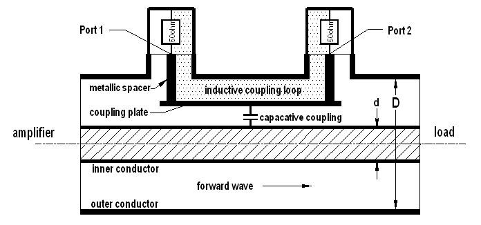
Fig. 1
The radio frequency (rf) power flowing from the amplifier to the load results in a radial electric field from the inner conductor to the outer conductor (ground) and a circular magnetic field between inner and outer conductor.
A small part of the electric field couples capacitively from the inner conductor to the coupling plate of the coupling loop. This leads to an rf voltage of this plate against ground and an rf current which flows over the electrically leading metallic spacers equally through the two 50 ohm resistors to ground. This voltage that arises due to the capacitive coupling of the forward wave is equal on both ports and positive. In the following we call this voltage +Vcap.
As already mentioned, the forward wave also generates a circular magnetic field, which is vertical and clockwise oriented to the direction of the propagation. This magnetic field is located around the inner conductor and is bound by the outer conductor. A small part of this magnetic field penetrates the coupling loop. The coupling loop, consisting of the coupling plate, the two metallic spacers, the two resistors and the ground between the resistors is building a closed circuit. The so-called magnetic flux through the coupling loop induces a current Iind in this closed loop. This current generates a positive voltage +Vind at port 1, flowing through the resistor at port 1. After passing this resistor, the induced current Iind flows along the ground to the resistor at port 2. The direction of this current through the resistor at port 2 is opposite to the current through the resistor at port 1. This leads to a negative voltage –Vind at port 2, before the current flows back to the coupling plate.
If one can obtain by an appropriate geometry, that Vcap and Vind are equal in amplitude and phase, this will result in twice the voltage on port 1, adding V cap and V ind, while adding Vcap and –Vind on port 2 will lead to zero voltage. In this case the forward wave couples a part of the transported power to port 1 while nothing of it couples to port 2.
For the reverse wave with the same direction of the E-field but contrary direction of the H-field it is vice versa. Here the capacitive and inductive coupling adds on port 2 while they extinguish each other on port 1.
On port 1 one only measures a proportional part of the forward wave and on port 2 only a proportional part of the reverse wave. Thus the directional coupler can separately measure the forward and reverse wave.
In practice you will never find ideal conditions as just described. If Vcap und Vind are not exactly equal, the forward wave will couple a small part of the forward power to port 2 as well. Similarly the reverse wave will couple a small part to port 1.
If for example the forward wave couples one thousandth of the transported power to port 1, the directional coupler has a coupling factor of –30 db. Consider further an example, where one measures –65 dB on port 2 (instead of ideally – infinity dB) because of a small diversity between capacitive and inductive coupling (even with an ideal matching of the main line without a reverse wave). In this case there is a difference in the coupling of port 1 and port 2 of 35 dB. This factor is called the directivity of a directional coupler, which is in this example 35 dB.
The directivity is a measure of how well capacitive and inductive coupling of a directional coupler are matched in amplitude and phase. We recommend a directivity of at least 30 dB, better 35 to 40 dB. After our explanations about the two voltages Vcap and Vind above, you can imagine that not only the geometry of the coupling loop but also the quality and equality of the two 50 ohm resistors have a strong influence on the directivity of the directional coupler.
To summarize, we have shown how a directional coupler works and specifically, how a perfect directional coupler is able to measure the forward and reverse wave separately. Additionally, we defined the parameter directivity of a directional coupler and its connection to a non-symmetric geometry.