Definition: What is a radio frequency (rf) directional coupler?
 An rf directional coupler is a measurement instrument that consists of a line section, inserted in one of the following rf-lines: Coaxial lines, waveguides, strip-lines, tri-plate-lines, wirelines and so on.
This line section is normally inserted between a transmitter (or generator, or amplifier) and its load. The load can be very different, for example an antenna, a plasma like inside a laser or in another vacuum vessel, a resonator of an accelerator, an ohmic resistor like a dummy load or something else.
It is characteristic for this line section that it not only contains the main line for the rf-energy transport but also a coupling line (or even more than one). With this coupling line(s) it is possible, to couple a part of the transported energy to two (or more) coupling ports. The value of the coupling can vary over a wide range. In a 3 dB coupler (or power splitter) 50 % of the energy goes to the coupling port, while for example in a 60 dB coupler only one millionth of the transported power is coupled out.
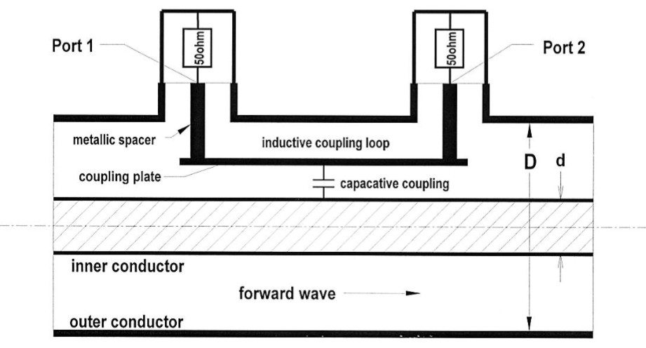 If power is transported for example from an amplifier to its load, this direction of the electromagnetic wave is called a forward wave. If this wave is transported in a coaxial line, this line has a characteristic impedance Zl, which can be calculated by the formula Zl = 60*ln(D/d) (Ω). D is the inner diameter of the outer conductor of the coaxial line, while d is the outer diameter of the inner conductor. D and d enclose the room where the rf wave is propagated. If the ratio of D/d is 2.3, the characteristic impedance of the line is rather precisely 50 Ohm. This is a very common value for rf-measurement equipment and also for coaxial lines. If the line between amplifier and load has an impedance of Zl = 50 Ω and the load has also 50 Ω real, then the forward wave will transfer its complete energy to the load. In this case the load is called matched. 50 Ω real means that the load has exactly 50 Ω without any inductive or capacitive components (Z = 50,0 Ω +/- j 0 Ω).
If the real part of the impedance of the load is not exactly 50 Ω and/or if the load additionally has inductive or capacitive components, a part of the forward wave will be reflected from the load. This leads to a reverse (or backward) wave from the load to the amplifier.
A directional coupler inserted between amplifier and load can separately measure the signals of the forward wave and of the reverse wave. If you want to learn what this is good for, continue reading with our tutorial Directional Coupler Applications.