Detectors
For our directional couplers, we have developed two main kinds of rf detectors, to rectify the coupled rf signals:
- A passive detector, which needs no supply voltages except the rf input voltage. These detectors are built for input powers from about 0.5W to 2W. They deliver an output dc voltage of normally 2V to a defined load.
- An active detector, which needs +/- 12V to 15V as a supply voltage. These detectors are built for input powers from about 50mW to a maximum of 0.5W.
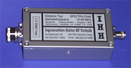
Technical data for our passive detectors
1. RF Input
Connector:............................N-male
Input level:..........................max. 1.5W
Nominal insertion attenuation:........at least - 40 dB
Operating frequency:..................13,56 MHz
2. DC Output
Connector:............................BNC-female
Load voltage:.........................2.00 Volt at 1W input to a load of 9,1 kΩ
Bandwidth:............................about 3 MHz
Short-circuit proof:..................yes
3. Dimensions, Weight and RoHS-Compliance
Dimensions of the detectors:..........about 150x64x31,5 mm (L,B,H)
Weight:...............................about 220 Grams
RoHS compliance:......................Yes
4. Technical description of a passive detector with a low pass input filter
 The rf signal of the coupled voltage is connected to an N male connector as an input of the detector. For personnel safety in case of a flash in the directional coupler to the coupling loop, the signal then passes a small ferrite transformer. One port of the secondary side of this transformer is on ground, while the RF path is isolated from the primary side of the transformer with more than 10 kV. Following the transformer there is a tunable low pass filter of 5th order.
For a working frequency of e.g. 13.56 MHz, all harmonic frequencies are damped by more than 30 dB up to 100 MHz. With the help of this filter, the impedance of a 50Ω resistor and its following rectifier and other circuits is transformed to 50Ω to the input of the detector (at nominal rf-level) with a matching of at least –40dB. The nominal rf-level is important, as the rectifying Schottky-Barrier diodes has to be open to see the influence of the components behind the diodes to the input.
After the rectifying, the signal has to pass another low pass filter to get rid of the RF ripple at the output. This second low pass is of 15th order and has a bandwidth of > 3 MHz, to guarantee a perfect output signal also for a pulsed rf with a high edge steepness while guaranteeing a suppression of more than 60 dB at 13.56 MHz. Finally the DC voltage at the BNC-female output is tuned to 2.00V with a load of 9.1 kΩ.
There exists also a version with a band pass filter for 13.56 MHz at the input instead of the low pass filter.
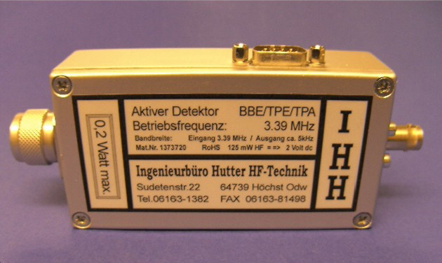
Technical data of our active detectors
1. RF Input
Connector:...........................N-male
Input level:.........................max. 500 mW
Nominal insertion attenuation:.......at least - 40 dB
Insertion attenuation at 250 MHz:....at least - 30 dB
Operating frequency:.................13,56 MHz
2. DC Output
Connector:...........................BNC-female
Load voltage:........................e.g. 1,000 Volt at 60 mW input to 9,1 kΩ
Bandwidth:...........................about 5 kHz
Dynamic range:.......................about. 20 dB
Short-circuit proof:.................yes
3. Power Supply System
Connector:...........................SUB-D 9-pin female
Positive supply voltage:.............+12VDC to +15VDC at pin 3
Ground:..............................0 Volt at the pins 8 + 9
Negative supply voltage:.............-12VDC up to -15VDC at pin 4
Additional output voltage:...........+ pin 2, - pin 7, ground decoupled by a choke
“Optional“ linear power output:......+ Pin 1, - Pin 6, ground decoupled by a choke
Spare pin:...........................Pin 5
4. Dimensions, Weight and RoHS-Compliance
Dimensions of the detectors:.........about 150x64x31,5 mm (L,B,H)
Weight:..............................about 220 Grams
RoHS compliance:.....................Yes
5. Technical description of an active detector with a broad band input matching
 The rf signal of the coupling port of the directional coupler is connected to an N male connector as an input of the detector. Different to the passive detector, the signal first passes an attenuator, which provides a broad band matching of -30 dB. For personnel safety in case of a flash in the directional coupler to the coupling loop, the signal then passes a small ferrite transformer. One port of the secondary side of this transformer is on ground, while the rf path is isolated from the primary side of the transformer with more than 10 kV. Following the transformer there is a tunable low pass filter of 5th order. For a working frequency of e.g. 13.56 MHz, all harmonic frequencies are damped by more than 30 dB up to 100 MHz. With the help of this filter, the impedance of an integrated circuit is transformed to 50 ohm to the input of the detector with a matching of about –50dB. The integrated circuit converts the remaining RF RMS voltage into a DC voltage at its output.
This voltage needs an offset compensation, which is done by a following amplifier. This remaining voltage is tuned at nominal input power of the detector with a variable amplification to 2.000 V with a defined load. Over a 1:1 buffer the voltage is given short-circuit proof to the BNC output connector and additionally over a symmetric choke to the Sub-D connector (Pins see above).
The active detectors are extreme long-term and temperature stable. With a heat treatment to 60°C a detector changed its output signal from 2.000 V to 1.998 V.
We calibrate all our detectors with a Rhode&Schwarz power meter with a frequency and temperature compensated True RMS Power sensor. The input powers of the detectors are calibrated with a network analyzer, which is used as the RF source and for a control of the power. After the network analyzer there is an amplifier, followed by an RF low pass filter and an external directional coupler. This coupler provides the input signals for the network analyzer to calculate the matching of the detector, which is connected to its output as well as a reference of the forward power as a control value.