Directional Couplers and Tutorials from the experts
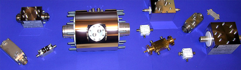
Welcome at IHH, the specialist for development and fabrication of customer-specified directional couplers of probably unreached accuracy. Different couplers from 10 kW over 20 kW, 30 kW, 40 kW, 50 kW up to 100 kW built by us are used in hundreds of plasma applications at 3.39 MHz, 13.56 MHz and 27.12 MHz. Various of our high-power directional couplers in the range of metric and VHF wave with pulsed powers up to 200 kW are used in scientific institutes like CERN and Paul Scherrer Insititute in Switzerland and Bessy, Institute for Plasmaphsics and GSI in Germany. The heavy ion cancer therapy in Heidelberg, Germany uses a 2 MW peak power coupler at 216 MHz made by IHH as well as some smaller ones. Our 150 kW cw couplers are in operation in many equipments worldwide. Different RF-detectors, according to the frequency and power of the couplers are part of our program.
For the standard industrial frequency of 13.56 MHz we have manufactured directional couplers of 1kW, 2kW, 3kW, 5kW, 10kW, 20kW, 30kW, 40kW and 50kW-100 kW, mainly for plasma applications. We also developed directional couplers of 3MHz, 250kW for an inductional heating and 500kHz-3MHz with 250 kW as well as 3.39MHz and 81.36 MHz couplers and 72MHz, 150 kW cw which are used for proton therapie, and 216MHz, 150kW and puls power for heavy-ion therapy. Other frequencies and powers can be realized according to customer needs.
The main connectors of our directional couplers use the connector systems N, High-Power-N, 7/16, 13/30,1 5/8“, 3 1/8“ up to 6 1/8“ EIA, while the outer couplings usually have N-connectors. BNC and other connectors can be realized according to customer needs.
Our directional couplers are adjusted with calibrated references to 1/100 dB, which is why we generally can guarantee a precison of 1/10 dB with a sharpness of directivity of bigger than 30 dB, typically even better than 35 dB.
Tutorials about Directional Couplers
We love to share our knowledge in our directional coupler tutorials. There you can learn what a directional coupler is, what it is used for, and how it works. For just getting a quick overview, simply read on below.
Definition: What is an RF directional coupler?
 An RF directional loop coupler is a measurement instrument which allows to separately measure the power which is transported from a generator or amplifier to its load on one coupling port of the loop and the reflected power (from the load to the generator) on the second port. Learn more.
What are directional couplers used for?
 As an rf dirctional coupler cannot only measure the amplitude of forward and reverse wave, but also the phase between these, there are two main applications they are used for: The amplitude of the forward wave can be used to regulate the power which is transported to the load, while the amplitude of the reverse wave can be used for a protection system of the complete equipment, by down-regulating the forward power, if the amplitude of the reverse wave reaches an excessive value. Together with the phase relation between forward and reverse wave, the complex impedance of the load can be calculated and together with an impedance matching network the complex impedance can be transformed to a matching of for example 50 Ohm for the generator. Learn more.
How does a directional coupler work?
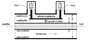 An RF directional loop coupler works by making use of both an inductive and a capacitive coupling at the two coupling ports. The geometry is chosen such that ideally the voltages due to inductive and capacitive coupling add at one port while they cancel each other at the second port for the forward wave. For the reverse wave this is vice versa. This allows a directional coupler to measure the forward and reverse wave separately at the two ports. Learn more.